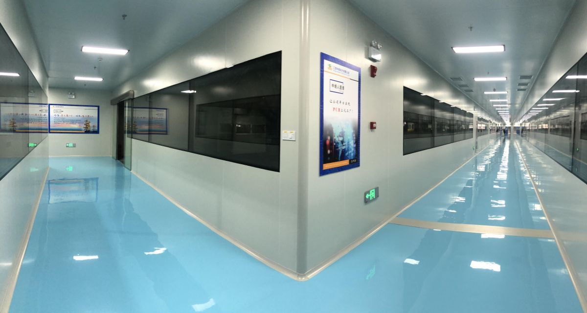
Clean room (also known as clean room or dust-free workshop) refers to a space with good air tightness that controls air cleanliness, temperature, humidity, illumination, pressure, noise and other parameters according to needs. According to domestic statistics, the pass rate of MOS circuit dies produced in an environment without cleanliness (non-dust-free environment) is only 10% to 15%, and the pass rate of 64-bit memory is only 2%. It is inseparable from a qualified dust-free environment, so we can see the importance of clean rooms for the development of modern industry. At present, clean rooms are widely used in the pharmaceutical industry, precision machinery, semiconductor, aerospace, atomic energy and other industries.
According to the form of air flow organization, clean rooms can be divided into two types: unidirectional flow and non-unidirectional flow. Non-unidirectional flow clean rooms, also known as turbulent flow or turbulent flow clean rooms, are mainly used in the electronics industry. The airflow in the room does not all flow in a single direction. Non-unidirectional flow airflow organization forms are the most common in the air purification industry, and are widely used in clean rooms of 1,000 to 300,000 (class6~calss9). Non-unidirectional flow clean rooms have several common features: terminal The filter (high-efficiency or sub-high efficiency) should be as close as possible to the clean room. It can be the air supply outlet or directly connected to the air supply outlet, or it can be connected to the air supply static pressure box in the room; The air mixed with clean air and indoor dust is effectively and orderly taken out of the clean room.
In general, the energy consumption of the purification air-conditioning system used in the clean room is much larger than that of ordinary household or commercial air-conditioning systems. The reason for this is the difference in load characteristics between the two. As far as the clean room is concerned, especially the clean room of the semiconductor industry, its load characteristics are: due to the large exhaust air volume and the need to maintain the positive pressure of the clean room, the fresh air volume is large, and the fresh air is compared with the indoor design air state. The large enthral difference requires a large cooling capacity; at the same time, because the production process requires the staff in the clean room to wear tightly wrapped clean clothes, for comfort and to prevent sweating, the design temperature of the clean room is generally around 20~23°C , which is lower than the design temperature of conventional air conditioners, which is also an important reason for the relatively large cooling load of the clean room. Production equipment generates a lot of heat and consumes a lot of cooling capacity. The sum of these three loads generally accounts for 70% to 95% of the total load. Therefore, the energy-saving measures for clean air conditioning systems in clean rooms should be reduced from the reduction of fresh air volume, control of air supply volume (that is, to control the reasonable number of air changes); make full use of the return air volume; choose low-resistance, high-efficiency air-conditioning and purification equipment and variable air volume fans Wait to start.
Based on an actual case, this paper introduces how to use CFD simulation to optimize the airflow organization of the clean room, and reduce the air supply volume as much as possible when the performance reaches the standard, so as to achieve the purpose of energy saving.
The clean room is used for the production of electronic components, requiring a dust-free grade of ten thousand (class7). Due to space limitations, this paper only presents the final optimized simulation results.
As shown in Figure 1 and Figure 2, the clean room size is 21mx19.4mx2.5m high, and 5x6=30 GS10 (1000CMH) high-efficiency air supply outlets are arranged on the top. The return air outlets are arranged at the bottom of two sides, and there are 16 return air outlets in total, 12 of which are H64 single-layer vertical adjustable louvers, and 4 are H88 single-layer vertical adjustable louvers.
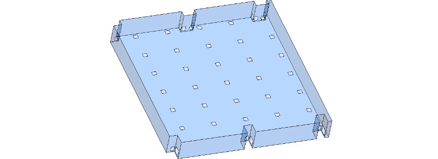
Figure 1 - Overall model

Figure 2 - Air supply port and air return port (colored parts in the figure)
Next, let's show the velocity distribution of the airflow in the clean room.
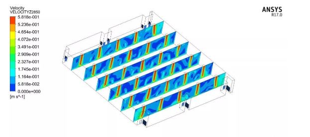
Figure 3 - Velocity distribution on different sections along the width direction
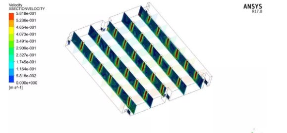
Figure 4 - Velocity distribution on different sections along the length
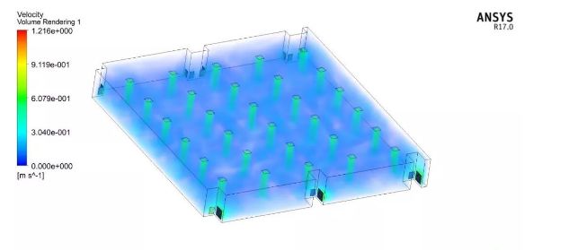
Figure 5 - Velocity distribution on the overall space
Figures 3 to 5 illustrate the velocity distribution in a clean room. For the clean room, whether it is a turbulent flow or a one-way flow, reducing the flow dead angle as much as possible is the first goal of the airflow organization. In order to clearly observe the airflow, we use velocity streamlines to show the flow of the entire clean room.
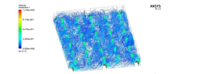
Figure 6 - Velocity streamlines on the overall space
Figure 5 is the velocity streamline of the entire clean room. We can clearly see that due to the reasonable design and arrangement of the air supply outlets, there are almost no dead angles in the entire space. When the airflow organization of the entire clean workshop has no dead angles, it is more conducive to the adjustment of the workstations in the workshop. At this time, the adjustment of the workstations does not need to consider the airflow organization.
In addition, we can also see from Figure 5 that the turbulent flow type, as the name suggests, is very chaotic and has many eddies. In order to better allow the dust particles generated in the room to be taken away by the clean air flow, the return air outlet is generally arranged at the lower part. Let's take a look at the velocity distribution on the section of the return air outlet.
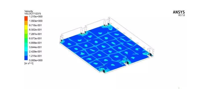
Figure 7 - Velocity cloud diagram on the section of the return air outlet
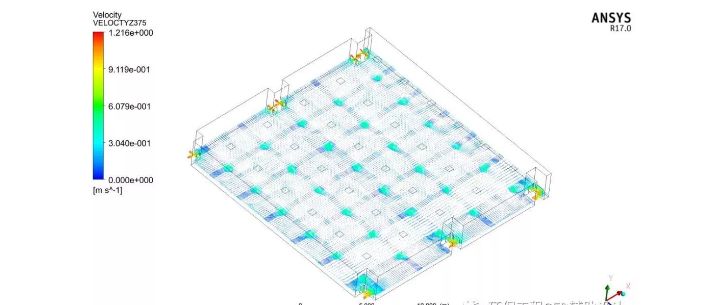
Figure 8 - Velocity vector diagram on the section of the return air outlet
It can be seen from Figure 7 and Figure 8 that, on the entire section, the area corresponding to the air supply port (projection area) has a higher velocity, and the velocity gradually decreases along the periphery, and the velocity at the return air port is the largest, because the return air port The sum of the areas is less than the sum of the areas of the air outlets.
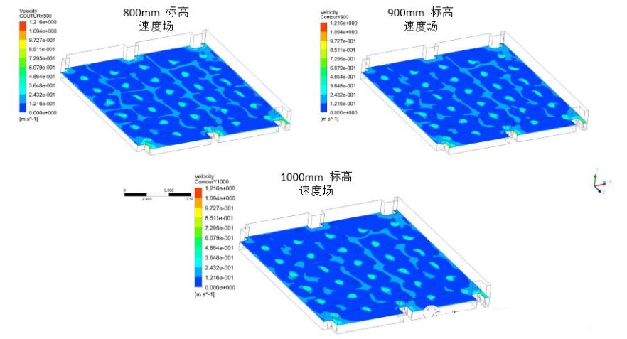
Figure 9-Velocity fields at 800mm, 900mm and 1000m elevations
Usually the working face is located at an elevation of 800mm to 1000mm. The above figure shows the velocity field at the elevation of 800mm, 900mm and 1000mm respectively. From the figure, it can be seen that there is no dead angle in the airflow in this interval, which means that all dust particles will As the airflow enters the purification system from the air return port.
To sum up, through the simulation of the airflow in the CFD clean room, this design meets the requirements of the clean room. There is no dead angle in the clean airflow, and the clean airflow is distributed throughout the room, achieving a clean effect.
From a theoretical analysis, the above three goals are contradictory. If the air flow has no dead angle, the vortex must be large; if the vortex is large, the air volume must be large. Because the end point of the design is to find a balance among the three goals. As a computer-aided method, CFD simulation can help engineers achieve design goals in the most efficient and economical way.
Welcome to contact whatsapp: +86 18038493643 for more clean room products purchase plans, you will enjoy low factory price with high quality.
Post time: Nov-25-2022

 +86-18038493642